
LEPTON FLIR SPARKFUN CODE
In an attempt to make my code as simple as possible, I created this sketch: #include īut I am just getting a string of mostly 0’s, with some other numbers in there. Is there anything obvious that I could be missing here? I can’t seem to get it to work at all, no matter what I try. However I am still getting garbled data over the SPI bus.
LEPTON FLIR SPARKFUN SERIAL NUMBERS
I can now get the Serial numbers and setup information out of the lepton, such as: beginTransmission I found out that I was wiring Sda and Scl to the wrong pins of the Due board, I should have had them wired to Pinds 20 and 21, and I was wiring them to the “SCL1” and “SDA1” pins. Pastebin is a website where you can store text online for a set period of time. is the number one paste tool since 2002. My code is here: It is a slightly modified version of some code that I found here. I am not hugely interested in video output, just still images, so it should be possible to do this even with the nano's 16mhz processor, is this correct? Right now, the "file" is the serial port, eventually it will be the TFT screen and an SD card. The documentation linked in the product page for the FLiR Lepton module has some example code for an. Then, send the entire image data to file. SparkFun has only tested the FLiR Lepton with the Raspberry Pi.

Grab a frame from the lepton, store it in SPI ram. However, I am not sure if I am understanding the code well enough to modify it to use with my SPI RAM, or even if a Nano can be used with the lepton. I believe this is due to the speed of SPI bus not being fast enough? Currently, I am using the serial port to print out the values, but this could be slowing things down. Usually 0's and random numbers, or some other nonsense output.

LEPTON FLIR SPARKFUN FULL
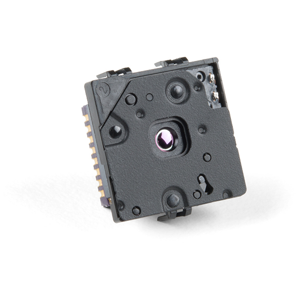
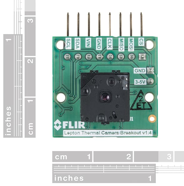
Low operating power, nominally 150 mW (Output Format: User-selectable 14-bit, 8-bit (AGC applied), or 24-bit RGB (AGC and colorization applied).Radiometric accuracy (35☌ Blackbody) Greater of:.1x FLIR Lepton® 2.5 - Thermal Imaging Module.When inserting it into the breakout board be sure to use proper personal grounding, such as a grounding wrist strap, to prevent damage the module. The Radiometric Lepton module is extremely sensitive to electrostatic discharge (ESD). Note: This kit comes in two separate parts and will need to be assembled once received. A few things to consider about this kit: the breakout board will accept a 3-5.5V input and regulate it to what the Lepton® wants, to read an image from the lepton module all you need is an SPI port, and to configure the camera settings you also need an I 2C port, although this is not required. Meanwhile, each breakout board in these kits provides the socket for the Lepton, on-board power supplies, 25Mhz reference clock (can be by-passed), power efficient 1.2v core voltage (can be by-passed), dual low noise LDO for 2.8V voltage (can be by-passed), 100 mil header for use in a breadboard or wiring to any host system. The Lepton 2.5 can output a factory-calibrated temperature value for all 4800 pixels in a frame irrespective of the camera temperature with an accuracy of +/-5?C. The Radiometric Lepton® LWIR module included in each Dev Kit acts as a sort of camera and packs a resolution of 80 × 60 active pixels into a camera body that is smaller than a dime and captures infrared radiation input in its nominal response wavelength band (from 8 to 14 microns) and outputs a uniform thermal image. All you need to do to get this kit set up, simply attach the Lepton® imager module into the provided breakout, connect the headers, and you will be seeing in full darkness in no time! This kit includes a breakout as well as the Lepton® 2.5 longwave infrared (LWIR) imager. Do you see what we see? With the FLIR Radiometric Lepton® Dev Kit v2 you will be able to bring FLIR's thermal imaging reliability and power to your Arduino, Raspberry Pi, or any ARM based development tool all in an easy to access breadboard friendly package.


 0 kommentar(er)
